STEERING SYSTEM
(Continued)
SHIFTING MECHANISM ADJUSTMENTS
The shifting mechanism has three different components that may need adjustment over time or rough usage. The Shifting Rod, the Lower Key(15), and the Upper Key(12).
To inspect and adjust the Shifting Mechanism, remove the cover panel at the rear of the dolly, below the Steering Post.
THE LOWER KEY
The Lower Key(15) needs to be adjusted first. This key must align with the Steering Post. When the Steering Post is "Straight" you should be able to shift into steer mode smoothly. To adjust this key, loosen the 4 screws underneath the dolly that hold the Lower Key assembly in place. The key assembly can rotate slightly to the left and right. Move it to make a smooth shift into Steer Mode, then tighten the 4 screws underneath.
THE UPPER KEY
The Upper Key(12) keeps the Upper Sprocket Assembly(2) locked in place when in crab mode. In order to have smooth shifting between crab and steer modes, the Upper Key(12) must be aligned properly with the Lower Key (15).
To adjust the Upper Key, loosen the two Upper Key Plate Screws(17) in Figure S7. Align the Upper Key Plate (18) so that shifting between crab and steer modes is smooth and straight, then tighten the two screws.
THE SHIFTING ROD
The Shifting Rod is located inside the Steering Post. See Figure S8. It must be set to the proper length to fully engage the Center Key(14) when shifting between crab and steer modes. If this is not correct, you may feel a 'bump' when turning the Steering Post past the straight position.
In Steer mode, the Upper Engagement Bracket(13) must be touching the Center Key Body(16) as shown in Figure S6. If there is a gap, the Shifting Rod must be lengthened. In crab mode, the Lower Engagement Bracket(19) must be touching the Center Key Body(16) as shown in Figure S7. If there is a gap, the Shifting Rod must be shortened.To adjust the Shifting Rod, see Figures S8 and S9
To make the adjustment, remove the Push Bar/Steering Post from the dolly.Locate the set screw on the Lock Nut through the Access Hole(20) near the end of the steering shaft. Loosen the set screw with a 5/64" hex wrench (some models use a 1/16" wrench). Next, place a flat screwdriver into the end of the Steering Post(22) and wedge it in beside the Lock Nut on the Shifting Rod to prevent the nut from turning, as shown. Then turn the Shifting Rod Knob(24) clockwise to shorten the Shifting Rod, or counter-clockwise to lengthen it. (One full turn is 1/18th of an inch.) The amount you need to adjust depends on the gap as described above for figures S6 and S7.
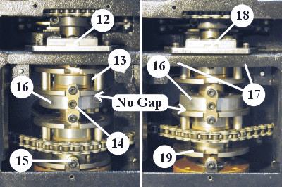
Figure S6 - Figure S7
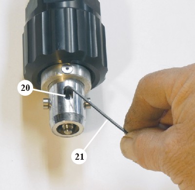
Figure S8
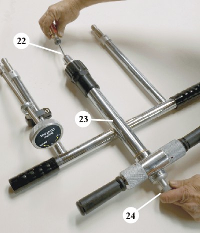
Figure S9
Figures S6 and S7
12 Upper Key
13 Upper Engagement Bracket
14 Center Key
15 Lower Key
16 Center Key Body
17 Upper Key Plate Screws
18 Upper Key Plate
19 Lower Engagement Bracket
Figures S8 and S9
20 Access Hole and Lock Nut (inside)
21 5/64" Allen Wrench (1/16" on some models)
22 Flat Screwdriver
23 Steering Post
24 Shifting Rod Knob
< Previous Page --- Next Page >
Copyright © 2019 Premier Studio Equipment, Inc.