VALVE SEAL REPLACEMENT
(Conntinued)
Remove the two Valve Rocker Assemblies(6) from the valve as shown in Figure V4.
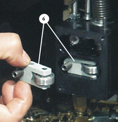
Figure V4
Using needle nose pliers, carefully remove either the Up Control Valve Piston(7) or the Down Control Valve Piston, whichever seal needs replacement, as shown in Figure V5, and place a paper towel or other stopper in the hole to prevent hydraulic oil from leaking out of the valve.
NOTE: Only remove and replace one piston at a time. The pistons are not the same.
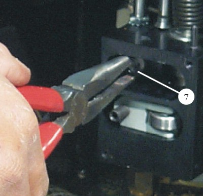
Figure V5
Replace the nylon piston seal on the end of the piston and replace the o-rings on the piston shaft using the Seal Replacement Kit, part no. 89-1251.
Figure V6
A Lower Valve Piston
B 1/4" x 3/8" O-Ring (2)
C Nylon Piston Seal (1 on each piston)
D Seal Retaining Screw
E 3/16" x 5/16" O-Ring (2 or 3)
F Upper Valve Piston
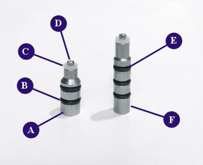
Figure V6
.
Using a lithium type grease, place a small amount of grease around the o-rings on the valve piston.
Making sure the piston hole in the valve is clear of debris, place the piston in the hole up to the first o-ring. Place a small punch and hammer at the end of the piston, as shown in Figure V6, then gently tap the piston repeatedly to vibrate the piston and o-rings into the hole without damaging them.
Repeat this process for the second piston if necessary.
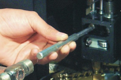
Figure V7
Replace the two Valve Rocker Assemblies, place the Rocker Pivot Pin(3) in the hole on the top of the valve and press in, aligning the two rocker assemblies. Press down until the pivot pin is all the way down, then tighten the Pin Set Screw(4).
Replace the Valve Cover Plate using the two screws.
Adjust the Up and Down Control Screws until they are just barely pressing the pistons in place to seat the seals, making sure the Boom Control Knob is in the '0' position. Do not tighten. These screws may need adjustment during the new break-in period. See Adjusting Boom Drift in the Maintenance section.
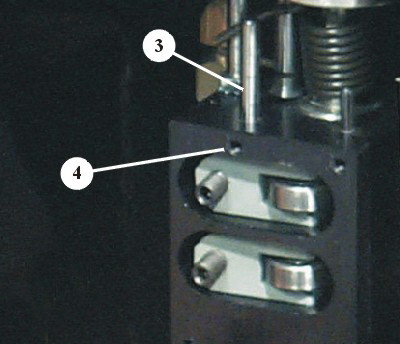
Figure V8
< Previous Page --- Next Page >
Copyright © 2019 Premier Studio Equipment, Inc.