SYSTEM OVERVIEW
(Continued)
MANUAL CHARGING: When charging with the Hand Pump(25), oil is drawn out of the Oil Tank(20), through the Suction Hose(23), and into the Hand Pump. The Hand Pump has two check valves inside it, one before the pump piston and one after it. These make sure the oil flows only in one direction through the Hand Pump. When pushing the Hand Pump down, oil is forced through the Pressure Hose(4) and into the Manifold(7), where it is filtered and sent to the Accumulator(9) and the Pressure Gauge(1). The Pressure Relief Valve prevents over-charging.
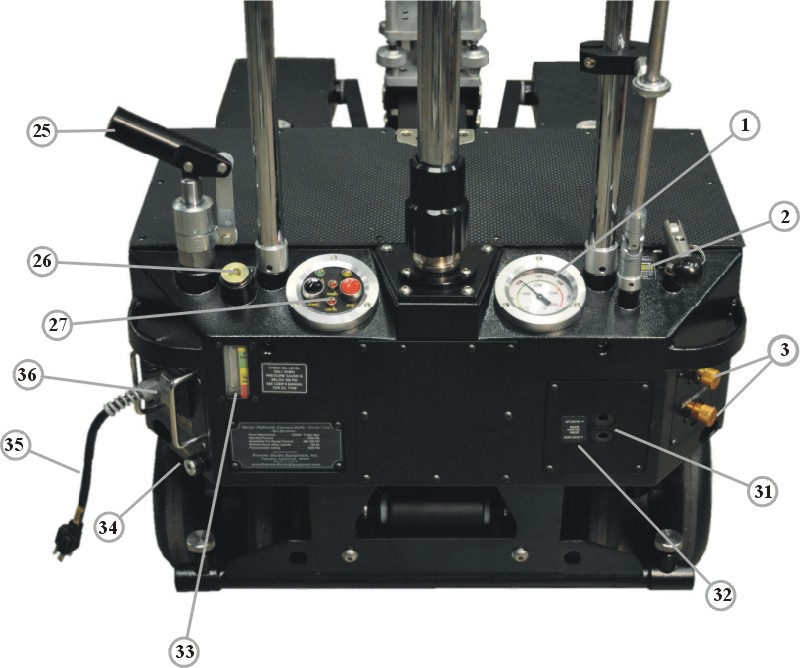
Figure H3
1 Pressure Gauge
2 Valve Connector
3 UP and DOWN Speed Limiter Valves
25 Hand Pump
26 Oil Fill Plug
27 Electric Control Panel
32 Boom Control Valve (behind access panel)
33 Oil Level Gauge
34 Oil Drain Plug
35 Power Cord
36 Circuit Breaker
BOOM UP MOVEMENT: When raising the boom up by turning the Boom Control Knob , oil flows out of the accumulator, through the Boom Control Valve(32), to the Up Speed Limiter Valve(3), which adjusts to set a maximum oil flow, and flows into the Boom Cylinder(11), raising the boom up.
BOOM DOWN MOVEMENT: When lowering the boom by turning the Boom Control Knob, oil is forced out of the Boom Cylinder(11) by gravity, to the Down Speed Limiter Valve(3), which adjusts to set a maximum oil flow, then through the Boom Control Valve(32) and to the Oil Tank(20).
< Previous Page --- Next Page >
Copyright © 2019 Premier Studio Equipment, Inc.