HYDRAULIC AND ELECTRICAL SYSTEMS
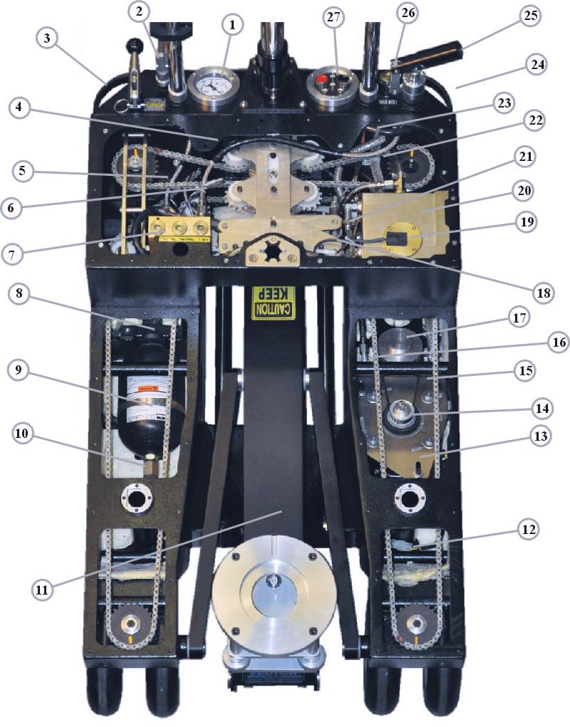
Figure H1
1 Pressure Gauge
2 Valve Connector
3 Speed Limiter Valves (rear)
4 Hand Pump Pressure Hose
5 Pressure Gauge Hose
6 Pressure Switch Connector
7 Manifold
8 Accumulator Hose Port
9 Accumulator
10 Accumulator Gas Valve Cap
11 Boom Cylinder (Under Boom)
12 Motor Cable Connector
13 Motor Adjustment Plate
14 Motor Pulley
15 Pulley Belt
16 Check Valve Assembly (before 2016)
17 Pump Pulley
18 Switch Connector
19 Oil Level Switch
20 Oil Tank (reservoir)
21 Vent Hose
22 Fill Hose
23 Hand Pump Suction Hose
24 Electric Power Panel (rear)
25 Hand Pump
26 Oil Fill Plug
27 Electric Control Panel
Note: Your model may have a slightly different configuration, depending on the year it was built.
< Previous Page --- Next Page >
Copyright © 2019 Premier Studio Equipment, Inc.