GETTING TO KNOW YOUR VECTOR DOLLY
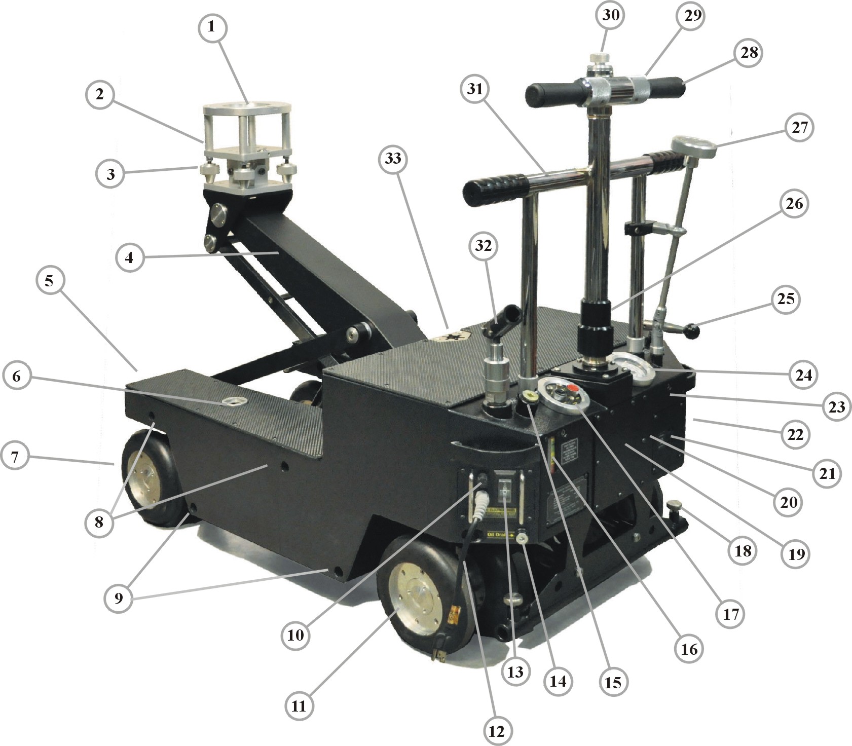
1 Mounting Plate
Mount a Camera Head, Camera Riser, or Low Shot Attachment here.
2 Leveling Head
Set this level each time the dolly is re-positoned to insure level panning.
3 Leveling Knob (4)
These knobs are used for leveling the head.
4 Boom Arm
This supports the Camera and other attachments as it moves up and down.
5 Front Mounting Holes
These 2 holes in the front are for mounting the optional Front Drop Bracket, and the Lift Rods.
6 Locking Utility Hole (2)
These sockets on both sides of the dolly are for mounting Seats and Utility Risers.
7 Front Wheel Pair
In Crab mode, these wheels turn the same as the steering post, in steer mode, they are locked in the straight position.
8 Upper Side Mounting Holes
This set of 2 holes is for mounting Platforms.
9 Lower Side Mounting Holes
These are the same as the upper holes, except the 6" Platform should not be used here unless the dolly is running on track. Attach the 10" platfroms here.
10 Low Voltage Fuse
This fuse is for the 24 volt switches and circuit board. This is a 1 amp fuse.
11 Rear Wheel Pair
In the Crab mode, these wheels turn the same as the steering post, in the Steer mode, they each turn at different rates, centering on the front of the leveling head.
12 Power Cord
Plug this in to the specified voltage to use the pump motor.
13 Circuit Breaker
This will trip when there is a power overload. Press "0" first, then "1" to Reset. Do not use this as an ON-OFF switch.
14 Oil Drain Plug
Drain the hydraulic fluid here. It will drain very slowly.
15 Oil Fill Port
This is where hydraulic fluid is added to the system. Use only specified oil.
16 Oil Level Gauge
This gauge indicates how much hydraulic fluid is in the reservoir when there is no charge
17 Electric Controls
These Push-Button Switches control the electric pump.
18 Rear Track Wheel Sockets
Attach the optional Track Wheels here and on the front Drop Down Bar.
19 Rear Access Cover
Remove this cover to access the Steer/Crab shifting mechanism.
20 Boom Control Valve Access Cover
Remove this cover to access the Boom Control Valve for maintenance.
21 Boom Control Adjustment Screws
These 2 holes are used to access the boom control valve adjustment screws using a 1/8" hex driver. See the Maintenance Section for proper adjustment.
22 Up & Down Speed Limiters
This set of 2 knobs control the maximum boom speed.
23 Push Bar Locking Screw
This set of 2 screws, left and right, hold the Push Bar in place.
24 Pressure Gauge
This gauge indicates the amount of hydraulic pressure in the system.
25 Parking Brake
Pull this lever up to set the dolly in a fixed position, do not engage it while the dolly is in motion. Push down to unlock.
26 Steering Post Locking Nut
This nut connects the Steering Post to the dolly frame.
27 Boom Control Knob
This knob controls the up and down boom movement with variable speed.
28 Steering Post
Use this to maneuver the dolly on level ground.
29 Shift Grips
These grips rotate to shift between CRAB and STEER modes.
30 Shift Knob
This knob is used to attach and detach the Steering Post from the shifting mechanism.
31 Push Bar
This bar is used for pushing or pulling the dolly under heavy load, such as up or down hill, and it holds the Boom Control Knob.
32 Hand Pump
This is used to charge the hydraulic system when no AC power is available.
33 Special Mount Socket
This socket is for special accessories. It is smaller than the Utility Socket. Seats and Utility Arms should not be placed directly in this socket.
< Previous Page --- Next Page >
Copyright © 2019 Premier Studio Equipment, Inc.